En stock Produit phare
DEK-OE-230AC/ 48DC/100
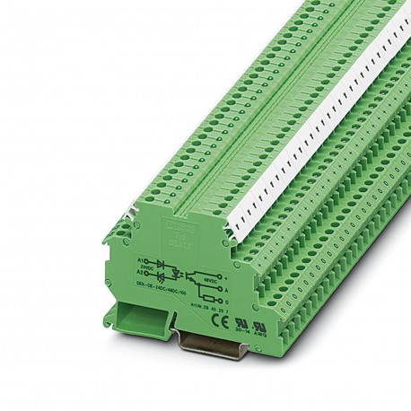
DEK-OE-230AC/ 48DC/100 2940210 PHOENIX CONTACT Solid-state relay terminal block
$0.00USD
4244 en stock
Spécifications clés
:Surge protection
Couleur:green (RAL 6021)
Profondeur:56 mm
Largeur:6.2 mm
Informations sur le fournisseur
Produits : 0
Habituellement expédié sous 2 à 3 jours ouvrables
Qualité garantie
Livraison rapide
Support technique
Spécifications techniques
| Paramètre | Valeur |
|---|---|
| Surge protection | |
| Couleur | green (RAL 6021) |
| Profondeur | 56 mm |
| Largeur | 6.2 mm |
| Hauteur | 80 mm |
| Isolation | Basic insulation |
| Application | Output function |
| Type de produit | Solid-state relay module |
| Filetage | M3 |
| Note de l'assemblée | in rows with zero spacing |
| Type de montage | DIN rail mounting |
| Mode de fonctionnement | 100% operating factor |
| Circuit de sortie | 2-conductor floating, 3-conductor ground-referenced |
| Famille de produits | DEK |
| résistance de sortie | approx. 22 kΩ (for 3-conductor operation) |
| Révision de l'article | 22 |
| Degré de pollution | 2 |
| longueur de dénudage | 8 mm |
| Méthode de connexion | Screw connection |
| Position de montage | any |
| Couple de serrage | 0.5 Nm |
| Informations sur la commande : | The housing is open on one side. The appropriate cover is D-DEK 1,5 GN (2716949). |
| circuit de protection | Reverse polarity protection |
| Plage de tension d'entrée | 207 V AC ... 253 V AC |
| Note sur l'application | Use of EB 80-DIK... bridges in the DEK terminal blocks: Absorption of humidity from the ambient air as well as an unfavorable tolerance between a larger number of DEK terminal blocks and the EB 80-DIK... bridge may cause (minor) expansion of the DEK housing. When the EB 80-DIK... bridges are used, therefore, it is recommended that these be disconnected after about 10 to 12 DEK terminal blocks and a wire bridge to the next DEK terminal block be inserted in their place. |
| Plage de tension de sortie | 3 V DC ... 48 V DC |
| Catégorie de surtension | III |
| Normes/réglementations | IEC 60947-5-1 |
| temps de réponse typique | 10 ms |
| Heure d'extinction typique | 20 ms |
| type de commutation de contact | 1 N/O contact |
| Fréquence de transmission | 3 Hz |
| Conception de la sortie numérique | electronic |
| Tension d'entrée nominale UN | 230 V AC |
| Affichage de la tension de fonctionnement | Yellow LED |
| Section transversale du conducteur AWG | 24 ... 14 |
| Limitation du courant continu | 100 mA |
| Tension de test (entrée/sortie) | 2.5 kV AC (Input/output) |
| Courant d'entrée typique à l'UN | 2.5 mA |
| Date de la dernière gestion des données | 03.05.2024 |
| Section transversale du conducteur rigide | 0.2 mm² ... 2.5 mm² |
| Température ambiante (fonctionnement) | -20 °C ... 60 °C |
| Section transversale du conducteur flexible | 0.2 mm² ... 2.5 mm² |
| Plage de tension d'entrée par rapport à l'UN | 0.9 ... 1.1 |
| Tension du signal de seuil de commutation « 1 » | ≥ 207 V |
| Température ambiante (stockage/transport) | -20 °C ... 70 °C |
| Signal de seuil de commutation « 0 », tension | ≤ 92 V |
| Chute de tension au courant continu limite maximal | ≤ 0.9 V |
| Signal de seuil de commutation « 0 » en référence à l’ONU | ≤ 0.4 |
| Signal de seuil de commutation « 1 » en référence à l’ONU | ≥ 0.9 |
Description du produit
Input solid-state relay terminal, input: 230 V AC, output: 3 - 48 V DC/ 100 mA, terminal width 6.2 mm
Caractéristiques principales
- Qualité de niveau industriel
- Conforme RoHS
- Certifié CE
- Garantie d’un an
Documents du produit
Fiche technique
Spécifications techniques et données de performance
Manuel d'utilisateur
Guide d'installation et d'utilisation


