En stock Produit phare
UST4C12EX
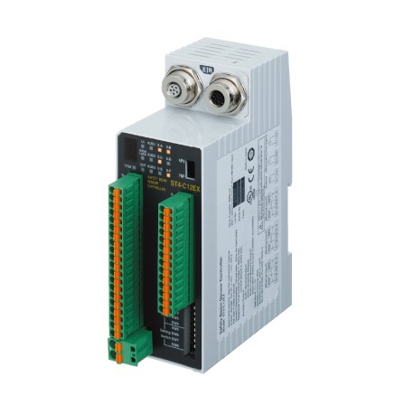
UST4C12EX ST4-C12EX PANASONIC Controller for ST4, high functional type
$0.00USD
4319 en stock
Spécifications clés
Article:Specifications
PFHD:Refer to the following table(Note: (Probability of dangerous failure per hour) depends on number of single beam sensorST4-A□connected to controller.)
MTTFD:More than 100 years (Note:Mean time to dangerous failure (in years))
Poids:Net weight: 240 g approxGross weight: 450 g approx
Informations sur le fournisseur
PANASONIC
Produits : 4316
Habituellement expédié sous 2 à 3 jours ouvrables
Qualité garantie
Livraison rapide
Support technique
Spécifications techniques
| Paramètre | Valeur |
|---|---|
| Article | Specifications |
| PFHD | Refer to the following table(Note: (Probability of dangerous failure per hour) depends on number of single beam sensorST4-A□connected to controller.) |
| MTTFD | More than 100 years (Note:Mean time to dangerous failure (in years)) |
| Poids | Net weight: 240 g approxGross weight: 450 g approx |
| Détails | Controller [High-functional] |
| Produit | Compact Type 4 Safety Beam Sensor |
| Matériel | Enclosure: ABS |
| Numéro de pièce | ST4-C12EX |
| Nom du produit | Compact Type 4 Safety Beam Sensor ST4 |
| câble de câblage | Terminal block connector: 0.2 to 1.5 mm2Power supply connector (A1, A2): 0.2 to 2.5 mm2 |
| Tension d'alimentation | 24 V DC +10-15 % Ripple P-P 10 % or less |
| temps de réponse | OFF response: 25 ms or lessON response: 90 ms or less (auto reset) / 140 ms or less (manual reset) |
| Numéro de produit | ST4-C12EX |
| Sorties auxiliaires | PNP open-collector transistor / NPN open-collector transistor (Set using output polarity selection switch)ST4-C11: one outputST4-C12EX: four outputs[PNP output]Maximum source current: 100 mAApplied voltage: same as the supply voltage (between auxiliary output and +V)Residual voltage: 2.5 V or less (at 100 mA source current)[NPN output]Maximum sink current: 100 mAApplied voltage: same as the supply voltage (between auxiliary output and 0 V)Residual voltage: 2.0 V or less (at 100 mA sink current)(Note) If the total current of the control outputs (OSSD1, OSSD2), auxiliary outputs, and muting lamp output exceeds 400 mA, the wiring resistance between the controller and the power supply should be 1 Ohm or less. In addition, if the total current is 400 mA or less, the wiring resistance between the controller and the power supply should be 2 Ohm or less. |
| Sortie de lampe de mise en sourdine | Available muting lamp: 24 V DC, 1 to 10 W(Note) If the total current of the control outputs (OSSD1, OSSD2), auxiliary outputs, and muting lamp output exceeds 400 mA, the wiring resistance between the controller and the power supply should be 1 Ohm or less. In addition, if the total current is 400 mA or less, the wiring resistance between the controller and the power supply should be 2 Ohm or less. |
| Terminal de connexion | Detachable spring-cage terminal |
| Consommation de courant | 120 mA or less (excluding sensor head ST4-Ax) |
| Normes applicables | IEC 61496-1/2 (JIS B 9704-1/2 / UL 61496-1/2) (Type 4), ISO 13849-1:2015 (Category 4, PLe), JIS B 9705-1 (Category 4), IEC 61508-1 to 3 (SIL3), IEC 62061 (SIL3), JIS C 0508-1 to 3 (SIL3), UL 1998, OSHA 1910.212, OSHA 1910.217 (C), ANSI B11.1 to B11.19, ANSI/RIA R15.06, ANSI/ISA S84.01 (SIL3)(Note) Complies with those standards only when the controller is used in combination with the sensor head ST4-x. |
| Tête de capteur applicable | ST4-Ax |
| Conformité à la directive de marquage CE | Machinery Directive, EMC Directive, RoHS Directive |
| Sorties auxiliaires : Mode de fonctionnement | ON when muting function is invalidOFF when muting function is validON when override function is invalidOFF when override function is validON when muting lamp is in normal conditionOFF when muting lamp is in abnormal conditionNegative logic of the control outputs (OSSD1, OSSD2) |
| Sorties de contrôle (OSSD 1, OSSD 2) | PNP open-collector transistor / NPN open-collector transistor Dual output x 1 system (Set using output polarity selection switch)[PNP output]Maximum source current: 200 mAApplied voltage: same as the supply voltage (between control output and +V)Residual voltage: 2.5 V or less (at 200 mA source current)Leakage current: 200 micro A or less (including power OFF condition)Maximum load capacity: 1 micro F (from no-load to max. source current)Load wiring resistance: 3 Ohm or less (between control output and load)[NPN output]Maximum sink current: 200 mAApplied voltage: same as the supply voltage (between control output and 0 V)Residual voltage: 2.0 V or less (at 200 mA sink current)Leakage current: 200 micro A or less (including power OFF condition)Maximum load capacity: 1 micro F (from no-load to max. sink current)Load wiring resistance: 3 Ohm or less (between control output and load)(Note) If the total current of the control outputs (OSSD1, OSSD2), auxiliary outputs, and muting lamp output exceeds 400 mA, the wiring resistance between the controller and the power supply should be 1 Ohm or less. In addition, if the total current is 400 mA or less, the wiring resistance between the controller and the power supply should be 2 Ohm or less. |
| Sorties auxiliaires : circuit de protection | Incorporated |
| Sortie de lampe de mise en sourdine : circuit de protection | Incorporated |
| Résistance environnementale : humidité ambiante | 30 to 85 % RH, Storage: 30 to 95 % RH |
| Résistance environnementale : résistance aux chocs | 300 m/s2acceleration in X, Y and Z directions three times each |
| Résistance environnementale : température ambiante | -10 to +55 ℃+14 to +131℉(No dew condensation or icing allowed),Storage: -25 to +70 ℃-13 to +158℉ |
| Résistance environnementale : Degré de protection | Enclosure: IP40 (IEC)Terminal: IP20 (IEC) |
| Résistance environnementale : résistance aux vibrations | 10 to 55 Hz frequency, 0.75 mm0.030 indouble amplitude or maximum acceleration 90 m/s2 in X, Y and Z directions for two hours each< |
| Résistance environnementale : résistance à l'isolation | 20 MOhm or more with 500 V DC mega between all supply terminals connected together and enclosure |
| Sorties de commande (OSSD 1, OSSD 2) : Mode de fonctionnement | ON when all beams of the connected ST4-Axs are receivedOFF when one or more beams of the connected ST4-Axs are interrupted(except during muting / override)OFF during lockout |
| Tête de capteur applicable : Nombre de connexions en série | Interference prevention possible when up to a maximum of 6 sets are connected(When the maximum of 3 controllers are connected together, interference prevention is possible for up to 18 sets) |
| Sorties de commande (OSSD1, OSSD2) : Circuit de protection | Incorporated |
| Résistance environnementale : tenue en tension | 1,000 V AC for one min. between all supply terminals connected together and enclosure |
Description du produit
ST4 Series High Functionality Control Unit
Caractéristiques principales
- Qualité de niveau industriel
- Conforme RoHS
- Certifié CE
- Garantie d’un an
Documents du produit
Fiche technique
Spécifications techniques et données de performance
Manuel d'utilisateur
Guide d'installation et d'utilisation


